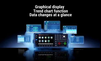
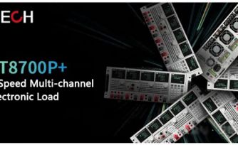
ITECH IT8700P+ Multi-Channel Electronic Load Enhances Dynamic Testing for Power Management Ics
As electronic devices continue to pursue higher intelligence and more compact form factors, one of the key pillars of overall system stability—the power management IC (PMIC)—is undergoing a quiet “efficiency revolution.”
On-board power management chips are becoming smaller yet more powerful. Through a high level of integration, multiple discrete power circuits that were once distributed across the board are now consolidated into a single chip, making power architectures more compact and streamlined.
At the same time, both power handling capability and operating speed have advanced rapidly, enabling PMICs to easily meet demanding requirements ranging from portable electronics to high-compute applications. The number of independently controlled output channels integrated into a single chip has also increased significantly. Acting like an intelligent “steward,” the PMIC precisely manages and orchestrates each power rail, achieving an optimal balance between performance and energy efficiency.
This ongoing evolution continues to propel electronic devices toward greater power, intelligence, and efficiency.
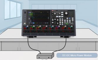
Power management ICs are responsible for supplying power to the components on the mainboard. To verify their load-driving capability, it is essential to evaluate the dynamic response performance at the output. Dynamic response time is a critical performance metric for power-related products. In simple terms, it measures how quickly a power management IC can respond to a sudden change in output load—such as when a system transitions from standby to full operation—and restore the output voltage to its normal regulation range.
A PMIC with insufficient load-driving capability may require increased power margin to ensure stability, which ultimately leads to inefficient use of system resources.
When testing the output dynamic response of on-board power management ICs, a low-power, high-speed DC electronic load is required. For PMICs with multiple power rails, ITECH’s IT8700P+ Series high-speed multi-channel DC electronic loads deliver outstanding performance. The IT8700 series is a classic ITECH product line with more than a decade of proven success, supporting up to 16-channel modules as well as master–slave parallel operation, and is widely used across industries such as power electronics and battery testing.
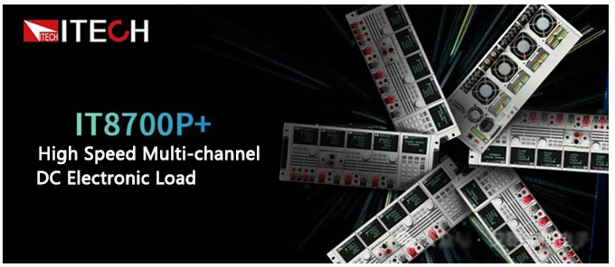
As the latest upgraded model of a proven classic, the IT8700P+ high-speed multi-channel DC electronic load delivers significantly faster dynamic response, achieving a current slew rate of up to 12 A/µs per module. The higher loop bandwidth enables precise current control with no overshoot, improving both test accuracy and efficiency.
Featuring three current ranges, the IT8700P+ provides higher measurement accuracy and lower ripple performance. In addition, the voltage and current measurement rates have been upgraded to 250 kHz, enabling the system to meet the high-speed load transient testing requirements of next-generation power management ICs.
Which parameters affect dynamic testing performance?
01 Current Slew Rate
When selecting a suitable electronic load for high-speed load transient testing, one of the most critical specifications to consider is the current slew rate, also known as the current rise/fall slope. It describes how fast the electronic load can change its current level and is expressed in A/µs. A higher slew rate indicates a steeper current ramp-up or ramp-down capability.
ITECH’s new-generation high-power electronic loads achieve a single-unit current slew rate of up to 45 A/µs, delivering outstanding performance among low-voltage electronic loads on the market. However, it is also important to note that most electronic loads with very high slew rates are typically rated at 6 kW or higher. While such performance is well-suited for high-current, high-power applications, it is not ideal for power management IC testing, where lower power levels and finer control are required.
The ITECH IT8700P+ Series multi-channel electronic loads achieve a maximum current slew rate of 12 A/µs within a low-power load matrix, making them an optimal choice for semiconductor and PMIC testing. The IT8733P+ (150 V / 120 A / 600 W) can reach 12 A/µs with just a single module, and the slew rate can be further increased through multi-channel master–slave parallel operation.
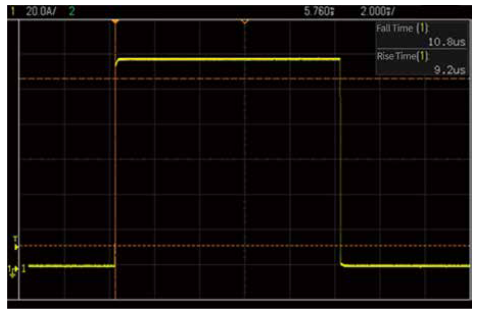
IT8733P+ module, 1A to 120A dynamic current curve, current slew rate 12A/us
02 Minimum Current Rise Time
In addition to current slew rate, another key—yet often overlooked—parameter of electronic loads is the minimum current rise time. When the output current of the power management IC under test is relatively low and does not require the electronic load to operate at its full current range, the load may not reach its maximum slew rate. In such cases, it becomes essential to evaluate whether the electronic load can still deliver strong dynamic performance under light-load conditions.
The minimum current rise time provides insight into the control loop bandwidth of the electronic load and more accurately reflects its dynamic frequency response capability.
The IT8700P+ Series significantly shortens the minimum current rise time even for small current steps. Delivering outstanding performance under both full-load and light-load conditions, it meets users’ testing requirements across a wide operating range.
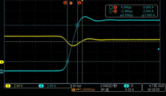
IT8733P+ module, 0.1A-10A current ramp-up, actual slope 1.07A/us
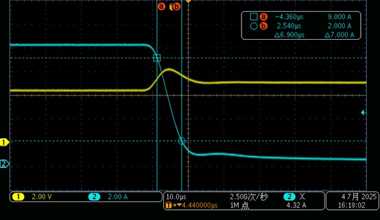
IT8733P+ module, 10A-0.1A current drop, actual slope 1.01A/us
ITECH Testing Solutions
In addition to
dynamic response testing, the IT8700P+ supports load regulation, efficiency,
and overcurrent/overload protection testing.
For multi-rail power management ICs and multi-output power systems,
it enables more in-depth and comprehensive evaluation of overall system
performance.
01 Synchronous testing of multi-output power supplies
Test Products:
Power supplies such as PC power supplies, server power supplies, and
industrial power modules, which typically provide multiple output voltages
simultaneously, including +12 V, +5 V, and +3.3 V.
Test Content:
Each channel of the multi-channel electronic load is independently assigned to
one output rail and loaded simultaneously. This approach accurately simulates
real operating conditions of the power supply.
- Cross regulation: Evaluates the impact on other output voltages when the load on one rail changes sharply.
- Overall efficiency: Measures input and output power under true multi-rail loading conditions to calculate system efficiency.
Advantages:
Compared with traditional sequential testing, this method significantly
reduces test time and can uncover potential issues that cannot be
detected through sequential tests.
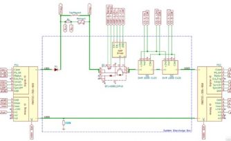
02 Redundant Power Supply System Testing (Main/Backup Configuration)
Test Products:
N+1 or 2N redundant power supply systems commonly used in
data centers and communication equipment.
Test Content:
Multiple channels are used to simultaneously simulate the
loads of multiple redundant power supplies, allowing evaluation of key
reliability metrics such as current sharing performance and fault switchover
time.
The ITECH IT8700P+ Series high-speed multi-channel DC electronic loads feature built-in LAN, USB, and RS232 interfaces and support the SCPI protocol, making them well suited for system integration. They can be applied to R&D and production-line testing of supercapacitors, fuel cells, lithium batteries, as well as high-speed AC-DC and DC-DC power supplies, including GPU power supplies and communication power supplies.