Comprehensive analysis of the application of SPS5000 semiconductor parameter test software in BJT testing
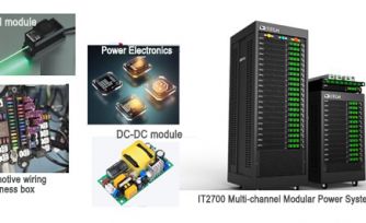
BJT, or bipolar transistor, commonly known as triode, is an electronic device with three terminals, made of three parts of semiconductors with different degrees of doping, and the charge flow in the transistor is mainly due to the diffusion of carriers at the PN junction and the drift motion. Bipolar transistors are capable of amplifying signals and have better power control, high-speed operation, and durability, so they are often used to form amplifier circuits or to drive devices such as speakers and motors, and are used in a wide range of applications such as aerospace engineering, medical devices, and robotics.
Structure and Main Characteristics of BJT
A bipolar transistor consists of three different doped semiconductor regions, which are the emitter region, base region and collector region. These regions are N-type, P-type and N-type semiconductors in NPN-type transistors and P-type, N-type and P-type semiconductors in PNP-type transistors. Each of these semiconductor regions has a pin terminal connected out, usually denoted by the letters E, B, and C for emitter (Emitter), base (Base), and collector (Collector).

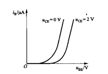
The DC input characteristic curve is obtained by measuring the relationship between IB and VBE at different VCE. When VCE=0V, the emitter junction is in forward-biased state and IC=0. When VCE increases, the collector junction enters reverse-biased state and starts to collect electrons, IC increases and the characteristic curve shifts to the right. These curves show the operating state of the transistor at different VCE.
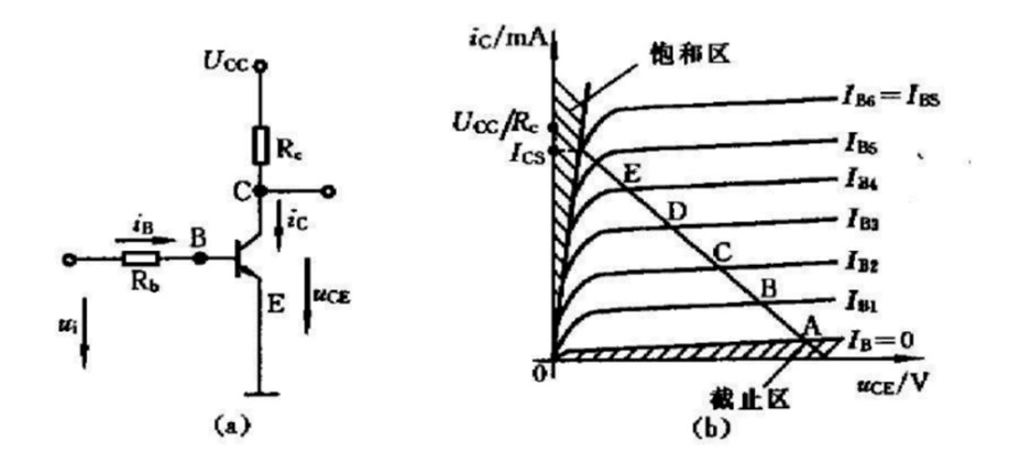
The DC output characteristic curve describes the relationship between the collector current IC and the collector-emitter voltage VCE. When VCE=0V, there is no collection at the collector and IC=0. As VCE increases, the collector junction reverse bias voltage increases and IC increases; when VCE is large enough, IC saturates and the characteristic curve enters a region parallel to the VCE axis. These curves are divided into three regions: the cutoff region, the amplification region, and the saturation region.
ITECH's professional SPS5000 semiconductor parametric test software is used in conjunction with the IT2800 graphical source measure unit to help users quickly realize semiconductor device qualification, device electrical performance parameters and device I-V characterization. The software supports DC, pulse, unidirectional and bidirectional scanning test modes, and with its intuitive graphical user interface, it can help university laboratories, semiconductor companies and research institutes to quickly perform device characterization without any programming knowledge.
China's BJT industry started earlier, there are many market participants, there is still a large demand for testing. In this paper, we will introduce how to realize BJT output characteristic curve test by SPS500 semiconductor parametric test soft and IT2800 graphical source measure unit.
Scenario Example
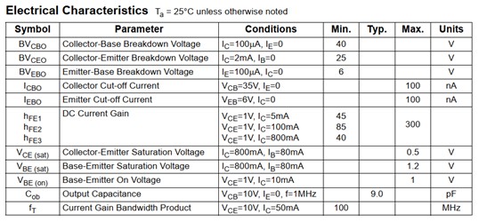
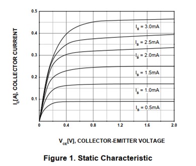
The SS8050 is an NPN type triode commonly used in low power amplification and switching applications. It is favored for its high current gain, low saturation voltage drop, and excellent switching characteristics.The SPS5000 tests the Ic-Vc characteristics of the SS8050 NPN BJT with an Ib sweep, and the specifications for this triode are:
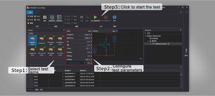
Users need to select the corresponding test items in the SPS5000 software, fill in the BJT specifications, scanning current, start and end voltage, etc.:
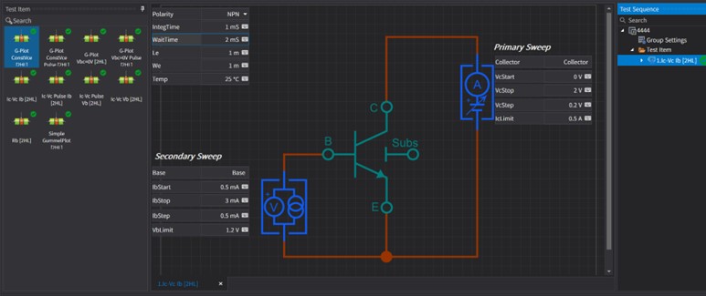
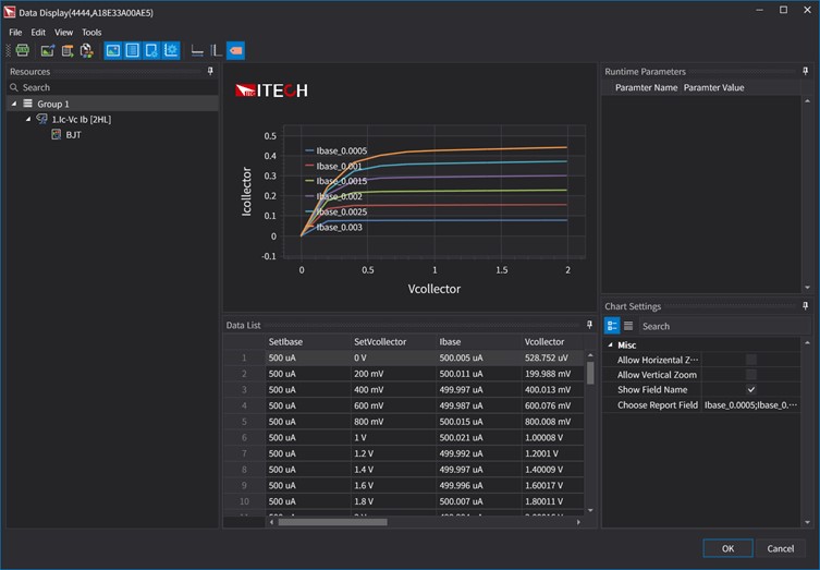
According to the wiring schematic of the test item, connect the IT2800 and the BJT to be tested, and then configure the corresponding machine in the software to connect the corresponding base and collector. After running the test project, a test report will be generated in the lower window of the test results. After double-clicking the test report, you can see the test curves and all the recorded parameters, and the user can make use of the various graphical analysis tools provided by the software, such as automatic scaling of the curves, constant value lines, area markers, tangent lines, distribution lines, etc., to quickly complete the analysis of the test results. Users do not need to export the chart with the help of other auxiliary tools, more convenient and quick. In addition, the software also supports multi-Y-axis function, and allows users to flexibly configure the data type of X-axis and Y-axis according to the analysis requirements, as well as choosing log or linear scale display format, so that the curve display is more intuitive and in line with the intent of the analysis:
Test Advantage: ITECH's SPS5000 software combined with the IT2800 high-precision graphical source measure unit can realize automated semiconductor static characteristic test, SPS5000 software built-in semiconductor model and a wealth of static index test items, you only need to carry out simple parameter configuration can quickly complete the test. When the test is completed, the host computer software can analyze multiple tests and display test parameters and curves to help engineers improve test efficiency.
The SPS5000 software provides built-in structural models of MOSFETs, BJTs, diodes, and other double-ended devices, with ready-to-use test items for each type of device. Testers can select a single test item for manual device verification or multiple test items to build a test sequence (for the same test wiring) to quickly perform multi-parameter analysis of a device according to the test requirements.SPS5000 also provides excellent data logging, curve depiction, and export and analysis functions, which is a professional test software that can help users to immediately improve the efficiency of the test.