|
As AI computing clusters and high-density data centers continue to scale, rack-level power delivery must support higher power, faster load changes, and tighter availability targets. In Open Rack architectures, the battery backup unit (BBU) is increasingly treated as an integral part of the rack power system rather than an optional peripheral. It must sustain the DC bus through an AC-input interruption, coordinate with the power shelf, and respond predictably under both normal and fault conditions.
This shift raises the bar for BBU verification. Conventional single-channel instruments, limited measurement accuracy, or fixed-voltage sources cannot reproduce the cell-level conditions needed to evaluate a modern battery management system (BMS). This article reviews the key BBU requirements associated with OCP Open Rack V3 (ORV3), explains the resulting test challenges, and presents a practical approach based on multichannel cell simulation.
1.OCP Open Rack V3 Raises the Bar for Rack-Level Backup Power
Open Rack V3 provides an open framework for rack mechanics, power delivery, thermal design, and system management. Within supported power architectures, a BBU shelf supplies DC power to the rack bus when the power shelf loses AC input. Current OCP documentation defines a narrow-range 48 V architecture and coordinated operation among the BBU modules, BBU shelf, power shelf, and rack monitor. Communication and control interfaces, including Modbus and CAN in current specifications, support status monitoring and system-level control. High-power ORV3 profiles also define quantitative backup targets; for example, a 5.5 kW BBU profile specifies at least 90 seconds at 5.5 kW and at least 240 seconds at 4 kW. The applicable values depend on the selected ORV3 contribution and system configuration. Hot-swap capability and redundant operation are equally important because the rack must remain stable when a module is removed or fails.
As a result, BBU validation is no longer limited to checking a few static electrical parameters. It now requires coordinated, multidimensional testing across operating states, dynamic transitions, communication behavior, fault response, and long-duration cycling. The test platform must provide the accuracy, synchronization, simulation fidelity, and coverage needed to connect cell-level behavior with rack-level performance.
2.Core BBU Test Challenges Under the ORV3 Framework
Challenge 1 Accurate and Synchronized Multichannel Cell Simulation
A BBU battery pack contains multiple series-connected cells, and the BMS continuously monitors the voltage of every cell. Verifying acquisition accuracy, channel consistency, and balancing strategy therefore requires simultaneous simulation of multiple cells with tightly coordinated channels. Independent benchtop supplies can introduce wiring complexity, channel-to-channel variation, and timing uncertainty that mask the behavior being measured.
Challenge 2 Realistic Battery Behavior
Battery behavior changes with state of charge, load, internal resistance, and operating history. A useful test system must go beyond fixed-voltage output: it should allow engineers to configure full-charge voltage, empty voltage, capacity, internal resistance, and equivalent-circuit parameters, then reproduce defined state-of-charge conditions. This model-based approach is essential for evaluating BMS estimation and control across the intended operating envelope.
Challenge 3 Controlled Fault Injection
Protection behavior must be verified under abnormal cell and wiring conditions. The test system therefore needs deterministic fault injection for conditions such as open circuit, short circuit, and reverse polarity. Equally important, engineers must be able to control when the fault is applied and observe how the BMS detects, reports, and responds to it.
Challenge 4 Long-Duration Cycling and Data Logging
Battery-life and control-strategy validation may require extended charge/discharge cycling while voltage, current, and power are recorded continuously. Stable long-term operation and synchronized multichannel logging are critical for identifying drift, intermittent events, and channel-to-channel differences that short tests can miss.
3.From System Requirements to Cell-Level Validation
ORV3 specifications define system-level expectations for discharge performance, power-shelf-to-BBU transition, communication, and reliability. Yet the ability of a BBU to meet those expectations ultimately depends on the interaction between its battery pack and BMS. Cell-voltage consistency, internal-resistance matching, state-of-charge estimation, measurement accuracy, balancing control, and protection-response time all affect whether the BBU can deliver energy through a millisecond-scale transition and maintain stable performance over repeated cycles. Effective verification therefore has to extend from the complete BBU down to the cell and BMS level. This is the central value of a multichannel cell simulation platform.
4.IT2600 Test Solution for ORV3 BBU Cells and BMS
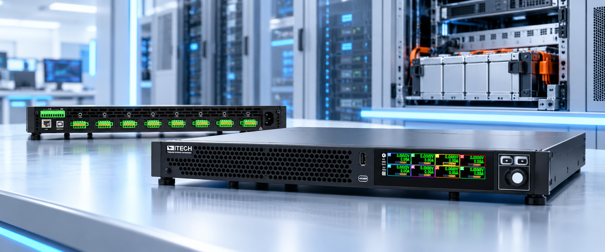
The ITECH IT2600 Multichannel Cell Simulation and Test Platform provides an integrated solution for cell- and BMS-level verification in ORV3 BBU development and production workflows.
Advantage 1 Eight Channels in a 1U High-Density Platform
The IT2600 integrates up to eight isolated channels in a compact 1U chassis. One instrument can therefore emulate the voltage of eight cells while reducing rack space, cabling, and synchronization errors associated with multiple standalone instruments. A touchscreen interface provides centralized configuration and monitoring for all eight channels.
Advantage 2 High Resolution and Accuracy for BMS Measurement Verification
The IT2600 offers voltage accuracy as low as ≤0.01% + 0.6 mV and current accuracy as low as ≤0.05% + 50 nA, with 0.1 mV voltage resolution and current measurement resolution down to 10 nA. This performance supports verification of BMS cell-voltage acquisition and balancing-current control. With both precision sourcing and measurement, the IT2600 functions as more than a battery simulator; it is a multichannel cell simulation and test platform.
Advantage 3 Comprehensive Battery Simulation Functions
The IT2600 provides fixed, battery simulation, list, battery charge, battery discharge, and battery cycling modes. In battery simulation mode, users can create or edit battery profiles that define full-charge voltage, empty voltage, capacity, internal resistance, and equivalent-circuit parameters. Series and parallel resistance values can be configured as part of the equivalent model, and completed profiles can be saved and reused for repeatable testing.
Advantage 4 Fault Simulation for Protection Verification
When operating as a battery simulator, the IT2600 can reproduce three representative fault conditions: open circuit, short circuit, and reverse polarity. These controlled fault states provide a repeatable way to verify BMS detection, protection logic, and recovery behavior without relying on physical battery faults.
Advantage 5 Battery Cycling and Synchronized Data Logging
For battery cycling, users can configure charge and discharge cutoff voltages, cutoff current, charge and discharge time, and cycle count. These controls support repeatable cycling profiles and control-strategy verification. For data logging, the recording interval, duration, and measurement items can be selected while voltage, current, and power are captured simultaneously across all eight channels.
Advantage 6 Series Expansion Beyond 200 Channels
Multiple IT2600 units can be combined for series-channel expansion, allowing a system to scale beyond 200 channels. One test platform can therefore address battery-pack structures ranging from tens to hundreds of cells, from compact BBU modules to larger BBU-shelf configurations. For long series strings, this scalability reduces platform rebuilds and enables coordinated simulation and measurement of large cell arrays.
5.Conclusion
As rack power density rises, ORV3 BBU validation is moving from basic electrical checks toward coordinated, system-oriented verification. Multichannel synchronization, precision cell simulation, controlled fault injection, and long-duration logging are now central to proving how the BMS and battery pack will behave when the rack depends on them. With eight channels in 1U, 0.1 mV and 10 nA resolution, comprehensive battery and fault simulation, scalable channel expansion, and flexible data logging, the IT2600 provides a practical foundation for efficient BBU R&D validation and production test.
ITECH specializes in power-electronics test and measurement, combining modular source-and-load instruments with proven automated test system capabilities. For AI data-center power validation, ITECH solutions include high-performance grid simulators, high-power bidirectional DC sources, high-speed dynamic loads, megawatt-scale system expansion, and regenerative operation. These capabilities help engineers reproduce AI workload power profiles and validate products such as solid-state transformers and power shelves across both R&D and manufacturing. Learn more on the ITECH website.
|