|
Repeatable Cell Emulation and Verification Against Applicable Safety Requirements
A cell approaches its charge limit, a temperature sensor lead opens,
or insulation resistance falls. Can the battery management system detect
the condition, issue the correct command and confirm that the protection
action has taken place? For 800V electric vehicles and high voltage
battery energy storage systems, these questions require repeatable
inputs and measurable results.
Cell emulation gives engineers control over individual cell voltages,
imbalance and selected fault conditions. Combined with temperature,
insulation, current and communication resources, it supports
verification of BMS measurement and control logic. Physical battery
tests and system safety assessments complete the evidence needed for the
intended application.
Higher
voltage makes the verification task more demanding
For a given cell chemistry, higher pack voltage usually requires more
cells in series. The term 800V does not define a fixed cell count: the
actual configuration depends on cell voltage and the pack operating
range. More channels and higher common mode voltage place additional
demands on isolation, wiring and consistent measurement across the
stack.
Automotive validation emphasizes charging behavior, vehicle
integration and fault response. Stationary storage adds sustained
operation, multiple battery strings and coordination with the power
conversion system (PCS) and supervisory controls. A bench that
reproduces these inputs helps engineers compare hardware and software
versions under the same conditions.
Why
real cells and cell emulation belong in the same test program
Real cells bring state of charge, temperature and aging into every
test. These factors are essential to battery validation, but they also
change the starting conditions. A simulator can reproduce a threshold
crossing or channel imbalance without first charging, discharging or
conditioning a physical pack. Engineers can use that repeatability to
isolate sampling errors, check diagnostic boundaries and reproduce
failures during regression testing.
Four practical
verification scenarios
Measurement
accuracy and channel consistency
Apply the same known voltage to each channel, compare BMS readings
and sweep the operating range in small steps near protection thresholds.
Record the input reference, reported value, sampling interval and
uncertainty. Resistance simulation checks the temperature sensing input;
chamber testing separately evaluates the hardware under actual
temperature exposure.
Fault detection and
protection execution
Ramp one channel toward a limit or inject a voltage step and sensing
circuit fault. Capture detection, alarm level, command, contactor
feedback and PCS response on a common time reference. This reveals
whether the BMS completes the protection sequence and recovers as
intended. A fault at the sensing interface validates control logic; high
energy short circuit and thermal runaway tests require the applicable
battery safety procedures.
Balancing and state
estimation
Set different channel voltages or model parameters to create
deliberate cell imbalance, then observe balancing enable conditions,
current and strategy changes. State of charge (SOC) and state of energy
(SOE) verification also need current inputs, a capacity or energy
reference and dynamic profiles. Static voltage outputs alone cannot
establish estimator accuracy, and an SOC result cannot substitute for an
SOE requirement.
Ripple response and
closed loop testing
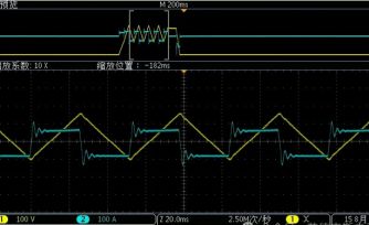
Controlled ripple helps evaluate the cell measurement front end,
filtering and diagnostic stability. IT2600 can superimpose voltage
ripple from 1 to 1000 Hz, up to 100 mVpp. Engineers should match this
range to the target disturbance. Cell input ripple tests, auxiliary
supply port tests and full electromagnetic compatibility (EMC) tests use
different ports and procedures.
In a hardware in the loop (HIL) setup, the cell simulator acts as an
output resource alongside a real time model, DUT communication and
acquisition. Channel synchronization and closed loop timing are verified
in the integrated setup.
All core electrical simulation and supply functions in an ITS5800 BMS
test setup can be implemented with ITECH hardware. The platform combines
cell, temperature and insulation simulation with module or pack voltage
inputs, current measurement validation and auxiliary power. Each
resource is selected for the DUT interface and required operating
range.
IT2600 integrates eight isolated channels in a 1U instrument for 0 to
6 V cell input verification. Multiple units can form configurations with
more than 200 channels and series operation up to 1200 VDC within the
rated system conditions. Independent channel control, source and sink
current capability, battery models and open circuit, short circuit and
reverse polarity simulation provide controllable inputs for sampling,
balancing and diagnostic tests.
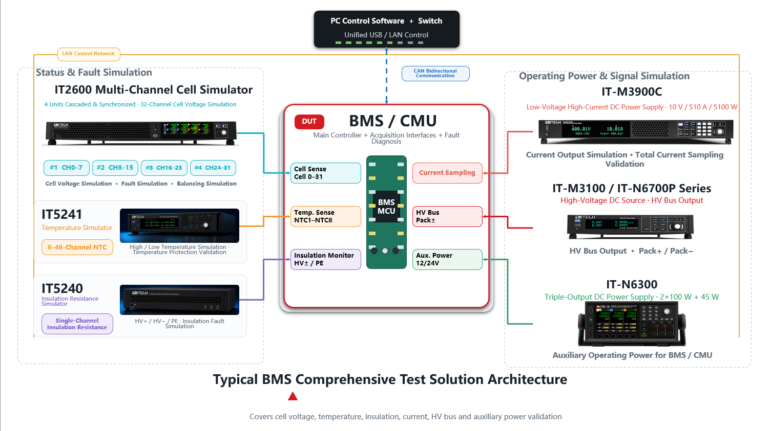
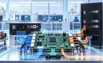
Figure 1. An example BMS and CMU verification configuration using
ITECH hardware. The low voltage, high current IT-M3900C model shown
serves current sampling validation; module and pack voltage resources
are selected separately, including IT6000C where required.
|
IT2600 cell simulation
|
Individual cell voltage, modeled behavior, balancing current and
selected cell terminal faults.
|
|
IT5241 resistance simulation
|
Resistance inputs representing temperature sensor signals.
|
|
IT5240 insulation impedance simulation
|
Controlled insulation conditions for BMS detection and diagnostic
logic.
|
|
IT6000C bidirectional DC power supply
|
Module or pack voltage/current simulation and source/sink operation
for charging and discharging scenarios.
|
|
IT-M3100 DC power supply
|
Programmable module or pack voltage input simulation within the
selected model rating.
|
|
IT-M3900C bidirectional DC power supply
|
Module or pack simulation using suitable voltage models; low
voltage, high current models support current sensor measurement
validation.
|
|
IT-N6300 triple output DC power supply
|
Independent auxiliary supply rails for the BMS, CMU and associated
circuits, including 12 V or 24 V where required.
|
|
ITS5800 BMS test system
|
Coordination of instrument control, DUT communication, acquisition,
test execution and result records.
|
Dedicated ITECH DC resources extend the setup to module and pack
voltage and current inputs. IT6000C and IT-M3900C provide bidirectional
sourcing and sinking; IT-M3100 supplies programmable voltage inputs for
suitable ranges. Selecting resources by DUT interface and test
requirement connects cell sensing verification with the wider BMS
electrical architecture. [16–18]
IT-N6300 provides three independently controlled auxiliary supply
outputs. ITS5800 coordinates these resources with DUT communication and
digital I/O. Match model ratings, isolation, accuracy and timing to the
test procedure and current sensing path. Temperature and insulation
input simulation verifies detection logic, while environmental and
dielectric withstand tests use separate procedures. [19]
Chinese
storage requirements provide measurable bench targets
GB/T 34131-2023 addresses battery management systems for electrical
energy storage. Clause 7.2.2 lists battery simulation equipment, and
normative Annex B specifies its requirements. The examples below show
how BMS functions translate into observable bench results. These are
Chinese standard requirements, not IEC or UL limits. [1]
|
Cell voltage acquisition
|
For cell voltage below 5 V: error no greater than 0.005 V; sampling
period no greater than 100 ms.
Clause 6.2.4 and Table 1
|
Reference voltage, BMS reading, measurement error and sampling
interval.
|
|
Level 1 alarm protection
|
After the alarm: issue a shutdown command within 300 ms and
disconnect the charge/discharge circuit within 5 s.
Clause 6.4.3.1
|
Alarm timestamp, command timestamp and actual circuit
disconnection.
|
|
Level 2 alarm protection
|
After the alarm: issue a command to reduce battery operating power
within 300 ms.
Clause 6.4.3.2
|
Alarm level, power reduction command and PCS response.
|
|
SOE estimation
|
Maximum permissible error of ±5%.
Clause 6.6.2
|
Voltage/current profiles, reference energy and the reported
SOE.
|
Timing must start at the event specified by the standard. Fault
injection to alarm, alarm to command and command to physical action are
different intervals. Annex B specifies ranges including 0 to 15 V for
cell simulation and 0 to 2000 V for string simulation. Equipment is
selected across the ITECH portfolio to match the required range,
accuracy, isolation and test conditions. For example, IT6000C includes
models up to 2250 V for high voltage string or pack tasks; cell inputs
are configured separately. Verify the complete setup against the
apparatus and measurement requirements, including calibrated measurement
uncertainty. [1, 16]
International
standards cover different levels of the system
For international projects, select requirements by the product being
evaluated and the destination market. IEC and ISO documents are
standards; UL and CSA documents support regional product assessment;
NFPA 855 addresses installation safety. UN Regulation No. 100 is a
vehicle approval regulation in jurisdictions applying it. Their legal
effect depends on adoption and project requirements.
GB/T 34131-2023
Storage BMS
|
CSA/ANSI C22.2 No. 340-2023
Battery management systems [2]
|
A direct BMS standard covering hardware/software that monitor and
control battery operation. Its scope and test requirements differ from
GB/T 34131.
|
GB/T 36276-2023
Storage lithium battery
|
IEC 62620:2014+AMD1:2023
Industrial battery performance [3]
|
Related cell and battery performance coverage; it does not replace
the storage specific Chinese specification.
|
GB 44240-2024
Storage cell and battery safety
|
IEC 62619:2022; IEC 63056:2020; UL 1973 [4–6]
|
Related battery safety coverage. IEC 63056 adds EES specific
requirements to IEC 62619 and covers nominal DC voltage up to 1500 V. UL
1973 includes stationary batteries.
|
GB/T 42288-2022
Storage station safety
|
IEC 62933-5-2:2025; UL 9540; NFPA 855 [6–8]
|
Related system and installation safety coverage, with different
assessment boundaries. UL 9540A evaluates thermal runaway fire
propagation. [9]
|
These references address related verification topics; the table does
not assert formal equivalence or interchangeable certification. GB/T
standards are recommended Chinese national standards, while GB
44240-2024 is mandatory. Its Clause 8.1 requires battery management to
detect and control abnormal voltage, temperature and current conditions,
linking BMS behavior to battery safety. [10–12]
For stationary storage, IEC 62619 and IEC 63056 address cells and
batteries, while IEC 62933-5-2 addresses the safety of the grid
integrated electrochemical storage system across its life cycle. BMS
bench evidence contributes to that assessment, together with battery,
converter and system tests. UL 1973 and UL 9540 likewise evaluate
different product levels. Cell emulation does not replace the physical
fire testing associated with UL 9540A or the installation assessment
under NFPA 855. [4–9]
Automotive
projects need their own approval and safety framework
For road vehicles, the ISO 26262:2018 series provides a functional
safety framework for safety related electrical and electronic systems.
BMS diagnostic and protection tests can contribute evidence for the
assigned safety requirements; the applicable Automotive Safety Integrity
Level (ASIL) follows the project hazard analysis and risk assessment. A
simulator does not confer an ASIL rating. [13]
UN Regulation No. 100 addresses electric powertrain safety and
rechargeable electrical energy storage system (REESS) approval for
relevant vehicle categories. Apply the amendment series and transitional
provisions required by the approval jurisdiction. Its vehicle and
battery safety assessment is distinct from stationary storage BMS
testing. [14]
European
battery rules add BMS data obligations
Regulation (EU) 2023/1542 adds legal requirements for batteries
placed on the EU market. Article 12 addresses stationary battery energy
storage safety and supporting test evidence. Article 14 requires up to
date data for the Annex VII parameters used to determine state of health
and expected lifetime in the BMS of stationary storage, electric vehicle
and light means of transport batteries. It also requires read only
access under the conditions specified in that Article. [15]
The verification plan should therefore cover data storage, update
behavior and access, alongside sensing and protection. Cell emulation
supports controlled electrical inputs; lifetime and state of health
assessment also need battery reference data and appropriate aging
evidence.
Make the
verification result repeatable and traceable
A useful BMS test record connects the requirement, applied input,
measured response and acceptance criterion. Cell emulation makes channel
errors and protection thresholds easier to reproduce. Integrated
temperature, insulation, current and communication resources extend that
evidence to the control sequence. Combined with real battery and system
tests, this approach helps ITECH customers evaluate BMS behavior under
controlled conditions and retain results that can be reviewed across
design revisions.
References
[1] GB/T 34131-2023 Source [2] CSA/ANSI C22.2 No. 340-2023 Source
[3] IEC 62620:2014+AMD1:2023 Source [4] IEC
62619:2022 Source
[5] IEC 63056:2020 Source [6] UL
1973 and UL 9540 Source
[7] IEC 62933-5-2:2025 Source [8] NFPA
855 Source
[9] UL 9540A fire testing Source [10] GB/T 36276-2023 Source
[11] GB 44240-2024 Source [12] GB/T 42288-2022 Source
[13] ISO 26262:2018 scope Source [14] UN
Regulation No. 100 Source
[15] Regulation (EU) 2023/1542 Source [16] ITECH IT6000C Source
[17] ITECH IT-M3100 Source [18] ITECH IT-M3900C Source
[19] ITECH IT-N6300 Source
Standards references checked on 14 October 2026. Use the editions and
amendments specified for the project and approval market.
|