How to Easily Simulate Three-Phase Voltage Imbalance with IT7900 - A practical guide engineers won’t want to scroll past
In the laboratory, you may often hear a sentence: “Three-phase imbalance is just an abnormal condition—no need to worry too much.” But in reality, the situations that actually cause equipment problems are precisely these “non-ideal conditions.” Today, we will use the IT7900 three-phase AC power supply / grid simulator to talk about a very “engineering” topic: how to simulate three-phase voltage imbalance.
In an ideal state, a three-phase system should have: equal voltage amplitudes, strictly 120° phase difference, and completely identical frequency.
But in the real world, situations often include: heavy single-phase loads,
uneven distribution, inconsistent line impedance, aging power distribution
systems, and reverse impact from grid-connected equipment. As a result, three-phase
voltage imbalance occurs.
What can happen if three-phase imbalance is not tested? Motors may experience
abnormal temperature rise, inverters may have severe current asymmetry, and
grid-connected equipment may malfunction. Therefore, three-phase imbalance is
not an “edge-case test,” but a must-test item.
In practical testing, it is usually divided into three cases.
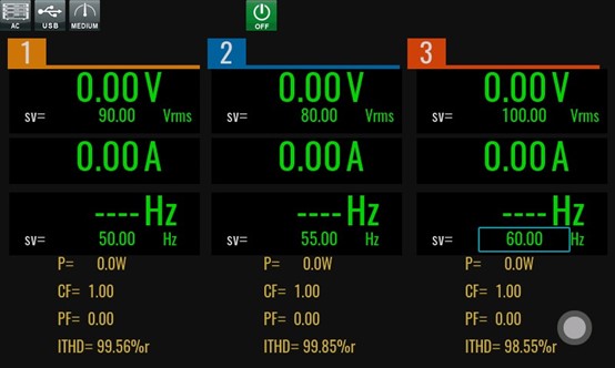
1. Voltage amplitude imbalance. This is also the most common. For example, Phase A voltage 400V, Phase B voltage 380V, Phase C voltage 360V. The phase is still 120°, and the frequency is the same.
2. Phase angle imbalance. For example, 118°, 121°, 121°. This is more stressful for grid-connected equipment. For a simulator, it tests the algorithm more rigorously.
3. Combined imbalance (extreme condition). Both voltage amplitude and phase deviate simultaneously, usually used for standard verification and so on.
The core advantages of the IT7900 grid
simulator perfectly match the requirements for simulating three-phase
imbalance. Each phase is independently controlled, allowing separate settings
for the voltage, frequency, and phase of A/B/C phases, rather than forcing
synchronous control of all parameters. This enables the device to realistically
reproduce an unbalanced grid. The IT7900’s output is very stable, with no
artificial jitter and clean dynamic changes, ensuring that testing the DUT is
not affected by disturbances from the simulator itself, guaranteeing pure and
rigorous test results. Therefore, it can be directly applied to grid-connected
equipment, motor systems, and energy storage PCS, making it suitable for
real-world grid-connected scenarios.
Using the IT7900 for three-phase imbalance is actually very simple. Below, we
directly present the three most commonly used laboratory scenarios.
Scenario 1: Three-Phase Voltage
Amplitude Imbalance (Used in 90% of tests)
Target example: Simulate a ±10% voltage imbalance grid
Voltage: Phase A 400 V, Phase B 360 V, Phase C 380 V, Frequency 50 Hz, Phase 0°
/ 120° / 240°
The setup is straightforward: turn on three-phase independent mode, set A/B/C
voltages separately, keep the frequency the same. Commonly used for: motor
tolerance, PCS grid adaptability.
Scenario 2: Phase Angle Imbalance
(“Algorithm Revealer”)
Example settings: Phase A 0°, Phase B 118°, Phase C 242°
Voltage remains the same, only the phase is adjusted. Especially suitable for:
grid synchronization testing, PLL stability verification.
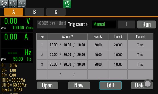
Scenario 3: Dynamic Imbalance
(Advanced), the real grid never stays “stuck in one state.”
The IT7900 Regenerative Grid Simulator can achieve: balanced → unbalanced → restore balance, through List +
remote communication + IO signal triggers, making it very suitable for grid
abnormal recovery testing.
Common pitfalls in testing:
- Looking only at the average value is not enough. Under three-phase imbalance, the average voltage may “appear normal,” but the negative-sequence components can already be severe. It is recommended to monitor simultaneously: per-phase RMS, phase currents, DC bus voltage. The IT7900 has a meter function with high-speed sampling, data logging, and waveform display, capturing detailed test data in real time for analysis. Customers do not need external data acquisition devices or oscilloscopes.
- Load type is critical. Purely resistive loads may not show issues, while motor or rectifier loads will amplify problems. This makes the IT7900’s grid simulation function even more necessary, providing both output and sink capabilities, suitable for various capacitive or inductive DUTs.
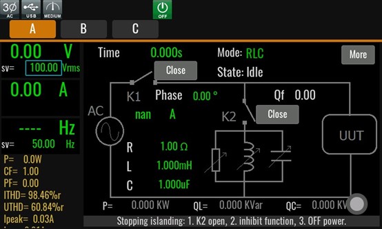
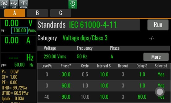
- Testing must closely reflect real-world applications. Equipment going off-grid does not necessarily mean it is “broken.” Many grid-connected devices will actively disconnect when imbalance exceeds thresholds or duration limits, which is actually “compliant behavior.” Widely used in energy storage / PCS, motor & drive systems, PV inverters, industrial variable-frequency drives, and grid certification labs. Our IT7900 grid simulator features islanding simulation and built-in IEC 61000 functions, allowing customers to easily verify whether DUTs meet regulatory requirements during R&D.
Three-phase voltage imbalance is not a sporadic abnormality, but a real grid condition that must be addressed. Using the IT7900, the “unstable grid” can be transformed into controllable, repeatable, and analyzable test conditions. The earlier problems are discovered in the laboratory, the less “blame” there will be on-site.